当前位置:网站首页>PWM output experiment
PWM output experiment
2022-07-21 19:42:00 【Three sloths】
One 、 Universal timer PWM summary
STM32 PWM working process

Input comparison register (CCRx) Save a value in , During counter counting , Same as CCRx Value comparison , Greater than ( Or less than ) Low potential will be generated , On the contrary, high potential is generated . The timer cycle counts to produce PWM wave , Its period is determined by ARR Values determine , The duty cycle is proportional to the period ratio of high-level duration ( from CCRx decision )
STM32 working process ( passageway 1 For example )

1、 Counter CNT The value of will be equal to CCR1 Value comparison , If CNT Greater than CCR1 A high level signal will be generated .
2、CCMR1 There are two bits , about PWM Under way , Used for setting up PWM Pattern 1 or PWM Pattern 2( The value ratio of the counter CCRx The value of is smaller than the effective level )
Pattern 1 With the model 2 The difference between :

3、 After comparison, it will be selected through the selector , choice 0 or 1 from CCER:CC1P Bit decided .(CCER:CC1P position : Input / Capture 1 Output polarity .0: High active ,1: Low level active .)
4、 The signal reaches the output enable circuit , adopt CCER:CC1E Bit enable (CCER:CC1E position : Input / Capture 1 Output enable .0: close ,1: open .) Thus, the signal is output to the corresponding pin .
( First of all PWM The mode determines the effective level , Let's see whether the effective level is high or low )
Take the up count configuration as an example
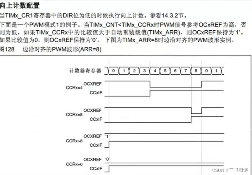
As you can see from the picture
Counter register ARR Count to 8 Count again when ,CCRx Set to 4 Then count to 0123 High level ( It works ), by 45678 Low when ( Invalid );CCRx Set to 8 be 0~7 When it is low, otherwise it is high .CCRx It can't be compared with ARR Otherwise, it cannot be produced PWM wave form .

ARPE=0, With cache , Effective next cycle , Count to F5 There will be an update event .ARPE=1,ARR Immediate effect .
Two 、PWM Output library function
void TIM_OCxInit(TIM_TypeDef* TIMx,TIM_OCInitTypeDef* TIM_OCInitStruct);
typedef struct
{
  uint16_t TIM_OCMode;//PWM Pattern 1 or 2
  uint16_t TIM_OutputState;// Output enable OR
  uint16_t TIM_OutputNState;
  uint16_t TIM_Pulse;// It's worth , Write CRRx
  uint16_t TIM_OCPolarity;// Compare the output polarity
  uint16_t TIM_OCNPolarity;
  uint16_t TIM_OCldleState;
  uint16_t TIM_OCNldleState;
}
  TIM_OCInitTypeDef;

  TIM_OCInitABC.TIM_OCMode=TIM_OCMode_PWM2;//PWM Pattern 2
  TIM_OCInitABC.TIM_OutputState=TIM_OutputState_Enable;// Compare output enable
  TIM_OCInitABC.TIM_Pulse=100;
  TIM_OCInitABC.TIM_OCPolarity=TIM_OCPolarity_High;// Output polarity :TIM High output polarity
  TIM_OC2Init(TIM3,&TIM_InitABC);// according to T The specified parameter initializes the peripheral TIM3 OC2
Set the comparison value function :void TIM_SetCompareX(TIM_TypeDef* TIMx,uint16_t Comparex);
Enable output comparison preload :
void TIMx_OCxPreloadComfig(TIM_TypeDef* TIMx,uint16_t TIMOCPreload);
The preload register that enables automatic reload allows bits :
void TIM_ARRPreloadConfig(TIM_TypeDef* TIMx,FunctionalState NewState);
3、 ... and 、 Write a PWM Output experiment
requirement : Use timer 14 Of PWM function , The output frequency is variable PWM wave , To drive LED The lamp , So as to achieve LED【PF9】 The brightness changes from dark to bright , And the process from light to dark , And cycle .
PWM Output configuration steps :
1、 Enable timer 14 And the related IO Port clock .
Enable timer 14 The clock :RCC_APB1PeriphClockCmd();
Can make GPIOF The clock :RCC_AHB1PeriphClockCmd();
2、 initialization IO The port is a multiplexing function output function :
GPIO_Init(); GPIO_InitABC.GPIO_Mode=GPIO_Mode_AF;// Reuse function
3、GPIOF9 Multiplexing maps to timers 14
GPIO_PinAFConfig(GPIOF,GPIO_PinSource9,GPIO_AF_TIM14);
4、 Initialize the timer :ARR、PSC etc. :TIM_TimeBaseInit();
5、 Initialize the output comparison parameters :TIM_OC1Init();
6、 Enable preload register :TIM_OC1PreloadConfig(TIM14,TIM_OCPreload_Enable);
TIM_ARRPreloadConfig(TIM14,ENABLE);
7、 Enable timer .
8、 Constantly changing the comparison value CCRx, Achieve different duty cycle effects :TIM_SetCompare1();
#include "pwm.h"
void TIM14_PWM_Init(u32 arr,u32 psc)
{
	GPIO_InitTypeDef GPIO_InitABC;// Structure
	TIM_TimeBaseInitTypeDef TIM_TimeBaseInitABC;
	TIM_OCInitTypeDef TIM_OCInitABC;

    RCC_APB1PeriphClockCmd(RCC_APB1Periph_TIM14,ENABLE);// Can make TIM14 The clock
	RCC_AHB1PeriphClockCmd(RCC_AHB1Periph_GPIOF,ENABLE);

	GPIO_InitABC.GPIO_Mode=GPIO_Mode_AF;// Reuse
	GPIO_InitABC.GPIO_OType=GPIO_OType_PP;// Push pull multiplex output
	GPIO_InitABC.GPIO_Pin=GPIO_Pin_9;//GPIOF9
	GPIO_InitABC.GPIO_PuPd=GPIO_PuPd_UP;// Pull up
	GPIO_InitABC.GPIO_Speed=GPIO_Speed_100MHz;// Speed 100Hz
	GPIO_Init(GPIOF,&GPIO_InitABC);// initialization PF9

	GPIO_PinAFConfig(GPIOF,GPIO_PinSource9,GPIO_AF_TIM14);

	TIM_TimeBaseInitABC.TIM_ClockDivision=TIM_CKD_DIV1;
	TIM_TimeBaseInitABC.TIM_CounterMode=TIM_CounterMode_Up;// Upcount mode
	TIM_TimeBaseInitABC.TIM_Period=arr;// Automatic reload load value
	TIM_TimeBaseInitABC.TIM_Prescaler=psc;// Timer frequency division

	TIM_TimeBaseInit(TIM14,&TIM_TimeBaseInitABC);// Initialize the timer TIM14

	TIM_OCInitABC.TIM_OCMode=TIM_OCMode_PWM1;//PWM Pattern 1
	TIM_OCInitABC.TIM_OCPolarity=TIM_OCPolarity_Low;// The active level is low
	TIM_OCInitABC.TIM_OutputState=TIM_OutputState_Enable;

	TIM_OC1Init(TIM14,&TIM_OCInitABC);

	TIM_OC1PreloadConfig(TIM14,TIM_OCPreload_Enable);
	TIM_ARRPreloadConfig(TIM14,ENABLE);

	TIM_Cmd(TIM14,ENABLE);//

}
int main(void)
{
  u16 led0=0;
  u8 dir=1;
	NVIC_PriorityGroupConfig(NVIC_PriorityGroup_2);// Set system interrupt priority group 2
	delay_init(168);// Initialization delay function
	uart_init(115200);// Initialize the serial port baud rate to 115200
	TIM14_PWM_Init(500-1,84-1);
//84M/84=1Mhz The counting frequency of , Reload value 500, therefore PWM The frequency is 1M/500=2Khz
	while(1)
	{
	delay_ms(100);
	if(dir) led0++;// Increasing
	else led0--;// Decline
	if(led0>300) dir=0;// arrive 300 after , The direction is decreasing
	if(led0==0) dir=1;// Descending to 0 after , Change the direction to incremental

	TIM_SetCompare1(TIM14,led0);// Modify the comparison value , Change the duty cycle
	}
}
PWM experiment
边栏推荐
- Differences among cookies, sessions, and tokens
- Lombok simplifies development
- L1-008 sum integer segments
- 【transformer】ViT
- NFS share
- 深度学习——(6)pytorch冻结某些层的参数
- 笔试强训第19天
- LeetCode:1260. Two dimensional mesh migration [one dimensional expansion + splicing]
- "PHP implementation of Domain Driven Design" - integration context [reprint]
- 无线定位技术实验二 TDOA最小二乘定位法
猜你喜欢

FPGA逻辑资源评估之BRAM(以Xilinx为例)

Trivy source code analysis (scanning the vulnerability information in the image)

342 NLP open source datasets in Chinese and English are shared

元素类型为 “resultMap“ 的内容必须匹配 “(constructor?,id*,result*,association*,collection*,discriminato?)“

Preparation of hemoglobin albumin nanoparticles encapsulated by Lumbrokinase albumin nanoparticles / erythrocyte membrane

NFS share

MySQL (2)

Recommended collection | practical operation, data console selection example

Poste technique | a40i les trois problèmes de logiciel de carte réseau les plus courants, analysez - les un par un pour vous

Classic examples of C language: 21-30 examples: insertion sort, Hill sort 1, quick sort, Hill sort 2, recursion, completion, Fibonacci sequence, common divisor and common multiple, judging the number
随机推荐
C语言学习
人事部门OKR案例:为同事创造最佳办公环境
Day009 circular structure (exercise)
GUN编译器的命令是g++:$ g++ -o prog1 prog1.cc
Résoudre l'erreur signalée: uncaught typeerror: impossible de lire les propriétés sous - jacentes (lire « installer»)
Technical post | the three most common network card software problems of a40i are analyzed for you one by one
Web3流量聚合平台Starfish OS,给玩家元宇宙新范式体验
Lombok simplifies development
Okaleido tiger NFT is about to log in to binance NFT platform, and the era of NFT rights and interests is about to start
Differences between functions, methods and interfaces
维密萎靡,曾经“性感”现在真的“凉了”!
Kubernetes technology and Architecture (V)
MySQL (2)
无线定位技术实验二 TDOA最小二乘定位法
【C 练习】宏实现交换数字二进制奇偶位
The reason why "typeerror: 'STR' object does not support item assignment" appears
unittest测试框架原理及测试流程解析,看完绝对有提升
PWM输出实验
Implementation method of SuperMap iclient for openlayers layer group control
Verilog grammar basics HDL bits training 03