当前位置:网站首页>Input and output characteristic curve and gm/id simulation curve of MOS tube (cadence ic617)
Input and output characteristic curve and gm/id simulation curve of MOS tube (cadence ic617)
2022-07-20 14:50:00 【Nara sunny snow】
Catalog
Establish simulation schematic diagram
stay Library Manager Create a new schematic diagram in
Click on File----New-----Cell View
mos Output characteristic curve
Simulation curves under different gate source voltages
mos Input characteristic curve of the tube
Simulation curves under different leakage sources
see mos Various parameters of the tube
see mos Other parameters of the tube
Graph of gate source capacitance versus gate source voltage
modify dc And Outputs Parameters
Under different channel lengths gmid_idw Image
( Detailed content , Please browse slowly , deficiencies , Please also make suggestions , We learn from each other )
Establish simulation schematic diagram
stay Library Manager Create a new schematic diagram in
Click on File----New-----Cell View
Choose your own location , Name at will , Select schematic , Click on ok.

Call out device
Method 1 : Yes press the shortcut key i, Then call up the device .
Method 2 : Directly on the interface search Mid search , Enter your name and press enter , Then select the device in the process library and right-click Add In stance, Then press enter .

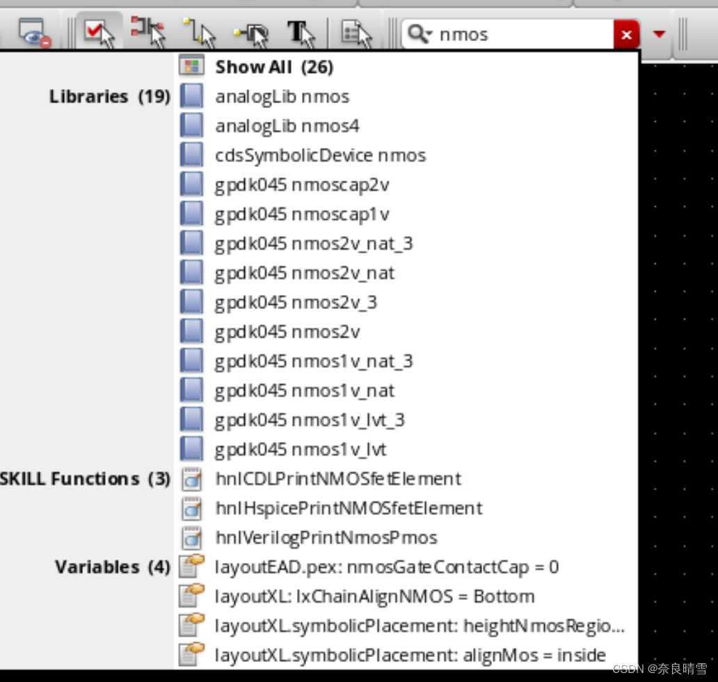
Selected devices :n mos2v vdd gnd vdc.( Everyone's craft library is different ,nmos The parameters of do not need to be modified )


vdc Medium DC voltage One for vds, One for vgs.
Connect and save the check
Shortcut key w attachment , Then click the save and check button .


Show no errors It shows that the schematic diagram has no problem and can be simulated .
Simulation preparation
establish ADE L Simulation
Click on Launch----ADE L

Select simulation file
Because this is our first simulation , We need to select the corresponding process library
Click on Setup-----Modul Library

Double click the second red box in the above picture , Click on ...(Browse), Choose the location of your own process library , And then click models---spectre, Finally, select the suffix corresponding to the process library .scs The file of ( Choose according to your own process library , Some are rf**.csc).


We can only select the process library we need to simulate .
And then in Section Select the corresponding box in this column tt.

add to vds and vgs
Click on Variables----Copy From Cellview

take vds Set to 1.8,vgs Set to 0.9, The purpose is to let them start in a saturated environment .

mos Output characteristic curve
explain : Flow through mos Tube current id With vds Change trend of .
Add output
Click on Outputs----To Be Plotted-----Select On Design, Then we click... In the schematic diagram mos The leakage pole of the tube , An oval circle appears, indicating that click to add it successfully , Then press ESC The oval circle disappears .

We right-click output , Click on Edit You can view its information .

Then we click the green simulation symbol , Start emulating .

The simulation results are as follows :
 If your simulation waveform doesn't come out , You can go back to the step of modifying your simulation library .
Simulation curves under different gate source voltages
If we want to get the trend of simulation curve under different gate source voltage , We need to do Parameter scanning .
We first close the simulation window , And then choose ADE L In the menu bar list Tools----Paramtric Analysis, Enter the following interface :

Then we start to modify the parameters :
choice vgs, Simulation range 0-1.8, Set to linear simulation , The simulation step is 0.3 , Then click the green button to start the simulation .

After loading the progress bar, the result will be displayed :

Next, we simulate the input characteristic curve .
mos Input characteristic curve of the tube
explain : Flow through mos Tube current id With vgs Change trend of .
Set up dc
Close the simulation window first , Right click dc---Edit--- take vds Turn into vgs---- Click on ok

Then we click the green simulation button , The simulation results are as follows :

Simulation curves under different leakage sources
Only one is shown here , Next, we can obtain multiple curves by parameter scanning ;
First, close the simulation interface , And then click Tools----Paramtric Analysis, Then set the parameters , choice vgs, Simulation range 0-1.8, Set to linear simulation , The simulation step is 0.3 , Then click the green button to start the simulation .


see mos Various parameters of the tube
Set up dc
Right click dc---Edit, Uncheck the Design Variable

Simulation
Directly click the green simulation button , Then return to the schematic , Right mouse click , choice Annotations----DC Operating Point, Then we can see that the specific parameters in the schematic diagram are displayed .

see mos Grid area
Continue in the schematic , Right mouse click ----Annotations-----Set up, Then jump out of a window :

stay Cell Select the pipe type in the schematic diagram , In the blank DC Operating Point Double click to select region, And then click Apply--ok--- Click on the pop-up window Apply .....-----ok, Finally, it is shown in the schematic diagram .


According to the picture :region=2, explain mos The tube is in the saturation zone .
see mos Other parameters of the tube
We are ADE L Click... In the panel menu bar Result---Print-------DC Operating Point ,r Then click mos tube ,mos Other parameters are listed .

Graph of gate source capacitance versus gate source voltage
choice vgs Variable
Close the simulation window above , stay ADE L Right click dc---Edit---- Check Design Variable----vgs

Modify the output (Outputs)
First delete the output

stay Outputs Right click in ----Edit, Add name c, And then click open, Write the expression of gate source capacitance , Select... In the pop-up window os, Then a small window pops out , We need to click on the schematic mos tube , Then select... From the small window list cgs, Copy the formula on the panel , Close the panel , Add the copied formula to c below , Click on OK.


Last Outputs The grid source capacitance inside is displayed ; Then click the green simulation button to run the simulation :

This picture looks a little strange , Let's edit the output c, Add a Minus sign , Then continue to run the simulation :

At this time, the image looks much better .
gmid_idw The graph of
modify dc And Outputs Parameters
Close other simulation windows , Right click dc---Edit-- Uncheck the Design Varibale---OK.


Simulation abscissa gmid, Ordinate idw Image
Delete c, Right click mouse ---Edit---- Enter a name gmid_idw, Then start editing the formula we need .
Click on open-----os--- Click on mos Take care of it ------ Select 【gmoverid】---- then 【CTRL + c】 Copy expression , Click below Function Panel In the search box of WA------ choice waveVsWave


The expression appears after clicking , At this time, the abscissa has been completed .

Then don't move , Start working on the ordinates , In the list list Select current id , Under the expression, click Green button


Then add it

w I can't find it in the small window , We need to close the small window , Click on the top right corner Tools----Browser, A window pops up .

Then we click on the coordinates 【+】, And then click 【instance 】, And then click 【M0】, Right pull out the information window , Choose the last one w(m)=...., Select and right-click , choice 【Calculator】

Then the expression comes out , Then we click the division sign next to the expression 【/】, We copy the calculated expression , Place the expression in y Axis coordinates there .

Click on the Apply, Finally, the total expression appears at the top , We copy it , Paste it under the corresponding name , Click on OK.

Click the simulation green button to run the simulation :

!! If the simulation does not show , Don't panic , We can right-click dc-----Edit--- Check Design variable , Then run it again .
We can use logarithm to display the image , Right click on the ordinate , Check 【Log Scale 】


Under different channel lengths gmid_idw Image
modify mos Tube length
Select... In the schematic mos tube , Press the shortcut key 【q】, take mos The length of the tube is changed to L, Then click the save and check button .

And then again ADE L Click on the 【Variables】----【Copy From Cellview】, take L Set to 200n.

Set scanning parameters
Click on ADE L In the menu bar 【Tools】---【Parametric Analysic】, Then set the following parameters :

Start emulating
Click the green simulation button , Start emulating , Logarithmic display :


thus , We completed the simulation , Browse so much , thank you for working so hard !
边栏推荐
- 完善镜像站配置信息 — 镜像站体验官
- vivo官网APP全机型UI适配方案
- mos管的输入输出特性曲线及gm/id仿真曲线(cadence IC617)
- 什么是蜜罐
- OneFlow v0.8.0正式发布
- Custom persistence layer framework myormframework (I) - JDBC analysis and solution ideas
- target文件夹里的资源无法被程序加载
- 定价随心、产品难辨真假、平台跑路,数藏市场还会火下去吗?
- ICLR 2022 | GNNAsKernel: 能提升任意GNN表达能力的通用框架
- 高端纯电SUV顶级产品,AION LX Plus与蔚来ES6如何选?
猜你喜欢


随机推荐
sprigboot中过滤器执行顺序源码解读
Interpretation of CBC mode and ECB mode
【MATLAB】基于油猴脚本和MATLAB下载原创力文档
股票开户首选,炒股交易开户佣金最低手机上开户安不安全
云原生、Intel Arch及云原生机密计算 3 大 SIG 在线分享!今天见 | 第 32-34 期
Cloud native core technology: implementation of service mesh istio
CB insights released seven trends in the AI industry: synthetic data and the rise of multimodal AI
今日睡眠质量记录75分
#导入Word文档图片# 内核同步与互斥
ICLR 2022 | GNNAsKernel: 能提升任意GNN表达能力的通用框架
康威定律——组织决定产品,领域驱动设计
科技云报道:不止于零信任,派拉“数字安全云战略”的野望
flink sql 配置 kafka 连锁一个多分区的topic 一直没连上也没报错,单分区的没问题
(0711-0717)本周开源软件安全大事记
三招从 20s 优化到 500ms
嵌入式开发:嵌入式基础——线程与任务
[论文阅读] Unpaired Image-To-Image Translation Using Cycle-Consistent Adversarial Networks
Cloud Native Core Technology: Service Mesh Implementation - istio
C#/VB.NET 添加多行文本水印到Word文档
Yuntu says digital asset chain: your God of digital asset property protection