当前位置:网站首页>[audio] transplant wm8978 audio codec driver based on STM32 I2S
[audio] transplant wm8978 audio codec driver based on STM32 I2S
2022-07-22 18:40:00 【ZHONGCAI0901】
Related articles
1.《【Audio】I2S transmission PCM Audio data analysis summary ( One )》
2.《【Audio】I2S transmission PCM Audio data analysis summary ( Two )》
3.《【Audio】 be based on STM32 I2S transplant WM8978 Audio Codec drive 》
1. WM8978 brief introduction
WM8978 Is a low power consumption , High quality Stereo codec , Designed for portable applications , Such as digital camera or digital video camera .
The chip integrates the preamplifier of stereo differential microphone , And includes speakers 、 Headphones and drivers for differential or stereo cable output . External component requirements are reduced , Because there is no need for a separate microphone or headphone amplifier .
WM8978 The functional block diagram of is as follows :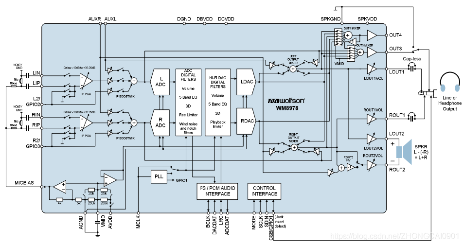
2. WM8978 Hardware connection
Use STM32F429+WM8978 Hardware platform , adopt I2S Interface To read and write audio data ,I2C Interface Send write command control WM8978 Related functions .
STM32F429 And WM8978 The pin connections of are as follows :
| STM32 Pin name | WM8978 Pin name | function | describe |
| GPIOB12 | LRC | I2S WS | Word selection , It is the audio data control signal output ,0: Left channel data ,1: Right channel data |
| GPIOD3 | BCLK | I2S BCLK | The serial clock , It's also called bit clock , Each bit of data corresponding to digital audio . |
| GPIOC2 | ADCDAT | I2S EXT_SD | control I2S Additional serial data pins for full duplex mode , For receiving audio data . |
| GPIOI3 | DACDAT | I2S SD | Serial data , Used to send audio data . |
| GPIOC6 | MCLK | I2S MCLK | When I2S When configuring the main mode , Use the master clock ( Individual mapping ) Output this additional clock . |
( remarks :I2C Is not the focus of this article , The introduction of it will be ignored here . a key :WM8978 Of I2C Can only write , Cannot read .)
3. STM32 I2S Configuration of
STM32 I2S The main configuration is :
- I2S relevant GPIO The initialization
- I2S Initialization of related registers
- I2S TX and RX Of DMA The initialization
- I2S relevant GPIO The initialization
STM32 Of I2S and SPI It's public. pin foot , So here we need to IO Set to I2S Pattern . these I2S The relevant functions of the pins of are described in detail in the table above , The following is the specific initialization code :
/** * I2S Bus transmission audio data port line  * WM8978_LRC -> PB12/I2S2_WS * WM8978_BCLK -> PD3/I2S2_CK * WM8978_ADCDAT -> PC2/I2S2ext_SD * WM8978_DACDAT -> PI3/I2S2_SD * WM8978_MCLK -> PC6/I2S2_MCK */
static void I2S_Gpio_Init(void)
{

	GPIO_InitTypeDef GPIO_InitStructure;

	/* Enable GPIO clock */
	RCC_AHB1PeriphClockCmd(I2S_WS_GPIO_CLK|I2S_BCLK_GPIO_CLK| \
                         I2S_ADCDAT_GPIO_CLK|I2S_DACDAT_GPIO_CLK| \
	                       I2S_MCLK_GPIO_CLK, ENABLE);

	GPIO_InitStructure.GPIO_Mode = GPIO_Mode_AF;
	GPIO_InitStructure.GPIO_Speed = GPIO_Speed_50MHz;
	GPIO_InitStructure.GPIO_OType = GPIO_OType_PP;
	GPIO_InitStructure.GPIO_PuPd = GPIO_PuPd_NOPULL;

	GPIO_InitStructure.GPIO_Pin = I2S_WS_PIN;
	GPIO_Init(I2S_WS_PORT, &GPIO_InitStructure);

	GPIO_InitStructure.GPIO_Pin = I2S_BCLK_PIN;
	GPIO_Init(I2S_BCLK_PORT, &GPIO_InitStructure);

	GPIO_InitStructure.GPIO_Pin = I2S_ADCDAT_PIN;
	GPIO_Init(I2S_ADCDAT_PORT, &GPIO_InitStructure);

	GPIO_InitStructure.GPIO_Pin = I2S_DACDAT_PIN;
	GPIO_Init(I2S_DACDAT_PORT, &GPIO_InitStructure);

	GPIO_InitStructure.GPIO_Pin = I2S_MCLK_PIN;
	GPIO_Init(I2S_MCLK_PORT, &GPIO_InitStructure);

	/* Connect pins to I2S peripheral */
	GPIO_PinAFConfig(I2S_WS_PORT,     I2S_WS_SOURCE,     I2S_WS_AF);
	GPIO_PinAFConfig(I2S_BCLK_PORT,   I2S_BCLK_SOURCE,   I2S_BCLK_AF);
	GPIO_PinAFConfig(I2S_ADCDAT_PORT, I2S_ADCDAT_SOURCE, I2S_ADCDAT_AF);
	GPIO_PinAFConfig(I2S_DACDAT_PORT, I2S_DACDAT_SOURCE, I2S_DACDAT_AF);
	GPIO_PinAFConfig(I2S_MCLK_PORT,   I2S_MCLK_SOURCE,   I2S_MCLK_AF);
}
I2S Initialization of related registers
It's mainly about setting up :I2S_AudioFreq = I2S_AudioFreq_44k// The sampling rate of audio data is 44.1KHzI2S_DataFormat = I2S_DataFormat_16b// The data width of audio data is 16bitI2S_Standard = I2S_Standard_Phillips// I2S Audio data transmission adopts Phillips I2S Standards for
The specific configuration code is as follows :
void I2S_Mode_Config(const uint16_t _usStandard,const uint16_t _usWordLen,const uint32_t _usAudioFreq)
{

	I2S_InitTypeDef I2S_InitStructure;
	uint32_t n = 0;
	FlagStatus status = RESET;

	/** * For I2S mode, make sure that either: * - I2S PLL is configured using the functions RCC_I2SCLKConfig(RCC_I2S2CLKSource_PLLI2S), * RCC_PLLI2SCmd(ENABLE) and RCC_GetFlagStatus(RCC_FLAG_PLLI2SRDY). */
	RCC_I2SCLKConfig(RCC_I2S2CLKSource_PLLI2S);
	RCC_PLLI2SCmd(ENABLE);
	for (n = 0; n < 500; n++)
	{

		status = RCC_GetFlagStatus(RCC_FLAG_PLLI2SRDY);
		if (status == 1)break;
	}

	/* Enable the CODEC_I2S peripheral clock */
	RCC_APB1PeriphClockCmd(I2S2_CLK, ENABLE);

	/* CODEC_I2S peripheral configuration */
	SPI_I2S_DeInit(I2S2_SPI);
	I2S_InitStructure.I2S_AudioFreq = _usAudioFreq;
	I2S_InitStructure.I2S_Standard = _usStandard;
	I2S_InitStructure.I2S_DataFormat = _usWordLen;
	I2S_InitStructure.I2S_CPOL = I2S_CPOL_Low;
	I2S_InitStructure.I2S_Mode = I2S_Mode_MasterTx;
	I2S_InitStructure.I2S_MCLKOutput = I2S_MCLKOutput_Enable;

	/* Initialize the I2S peripheral with the structure above */
	I2S_Init(I2S2_SPI, &I2S_InitStructure);
	I2S_Cmd(I2S2_SPI, ENABLE);

	/* Configures the full duplex mode for the I2S2 */
	I2S_FullDuplexConfig(I2S2_ext, &I2S_InitStructure);
	I2S_Cmd(I2S2_ext, ENABLE);
}
- I2S TX and RX Of DMA The initialization
WM8978 Audio Codec The driver needs to implement 2 Features : Play and record , So there will be a lot of data to send and receive . In order to reduce CPU The burden of , You need to use I2S Of TX and RX Of DMA.
??? Why did you choose DMA1 Stream4 Channel0 and Stream3 Channel3???
The screenshot below is DMA Functional block diagram , We need to use it to I2S Peripheral data received in memory , Send the data in memory to I2S peripherals . We need to choose the corresponding hardware according to the peripherals DMA Of stream and channel.
According to the hardware connection , It uses SPI2 Hardware interface reuse I2S2. Due to the use of I2S Full duplex function , And through I2S2_EXT To receive data , So here we choose DMA1 Of I2S2_EXT_RX receive data .I2S2_SD_TX The pins are multiplexed SPI2_TX, So here we choose SPI2_TX send data . That's it Why did you choose DMA1 Stream4 Channel0 and Stream3 Channel3? Here is SMT32 DMA1 The mapping table :
Here is TX DMA An example of initialization of ,RX DMA Initialization is the same process . The main steps are as follows :- Can make DMA The clock of
- Specify the data storage address of peripherals and memory
- To configure DMA Related attribute parameters of
- Set up DMA Interrupt parameters , Interrupt to indicate whether the data transmission is completed .
void I2Sx_TX_DMA_Init(const uint16_t *dmaM0Addr,const uint16_t *dmaM1Addr,const uint32_t num)
{

	NVIC_InitTypeDef   NVIC_InitStructure;
	DMA_InitTypeDef  DMA_InitStructure;

	/* Enable the DMA clock */
	RCC_AHB1PeriphClockCmd(I2Sx_DMA_CLK, ENABLE);

	/* Configure the DMA Stream */
	DMA_DeInit(I2Sx_TX_DMA_STREAM);
	while (DMA_GetCmdStatus(I2Sx_TX_DMA_STREAM) != DISABLE){
    }// wait for DMA1_Stream4 Configurable

	DMA_ClearITPendingBit(I2Sx_TX_DMA_STREAM,DMA_IT_FEIF4|DMA_IT_DMEIF4|DMA_IT_TEIF4|DMA_IT_HTIF4|DMA_IT_TCIF4);// Empty DMA1_Stream4 All interrupt flags on the

	/*  To configure  DMA Stream */
	DMA_InitStructure.DMA_Channel = I2Sx_TX_DMA_CHANNEL;  // passageway 0 SPIx_TX passageway
	DMA_InitStructure.DMA_PeripheralBaseAddr = (uint32_t)&I2S2_SPI->DR;// The peripheral address is :(u32)&SPI2->DR
	DMA_InitStructure.DMA_Memory0BaseAddr = (uint32_t)dmaM0Addr;//DMA  Memory 0 Address
	DMA_InitStructure.DMA_DIR = DMA_DIR_MemoryToPeripheral;// Memory to peripheral mode
	DMA_InitStructure.DMA_BufferSize = num;// Data transmission volume
	DMA_InitStructure.DMA_PeripheralInc = DMA_PeripheralInc_Disable;// Peripheral non incremental mode
	DMA_InitStructure.DMA_MemoryInc = DMA_MemoryInc_Enable;// Memory incremental mode
	DMA_InitStructure.DMA_PeripheralDataSize = DMA_PeripheralDataSize_HalfWord;// Peripheral data length :16 position
	DMA_InitStructure.DMA_MemoryDataSize = DMA_MemoryDataSize_HalfWord;// Memory data length :16 position
	DMA_InitStructure.DMA_Mode = DMA_Mode_Circular;//  Use circular mode
	DMA_InitStructure.DMA_Priority = DMA_Priority_High;// High priority
	DMA_InitStructure.DMA_FIFOMode = DMA_FIFOMode_Disable; // Don't use FIFO Pattern
	DMA_InitStructure.DMA_FIFOThreshold = DMA_FIFOThreshold_1QuarterFull;
	DMA_InitStructure.DMA_MemoryBurst = DMA_MemoryBurst_Single;// Peripheral burst single transmission
	DMA_InitStructure.DMA_PeripheralBurst = DMA_PeripheralBurst_Single;// Memory burst single transmission
	DMA_Init(I2Sx_TX_DMA_STREAM, &DMA_InitStructure);// initialization DMA Stream

	DMA_DoubleBufferModeConfig(I2Sx_TX_DMA_STREAM, (uint32_t)dmaM0Addr, DMA_Memory_0);// Dual buffer mode configuration
	DMA_DoubleBufferModeConfig(I2Sx_TX_DMA_STREAM, (uint32_t)dmaM1Addr, DMA_Memory_1);// Dual buffer mode configuration

	DMA_DoubleBufferModeCmd(I2Sx_TX_DMA_STREAM, ENABLE);// Double buffering mode is on

	DMA_ITConfig(I2Sx_TX_DMA_STREAM,DMA_IT_TC,ENABLE);// Turn on transmission completion interrupt

	SPI_I2S_DMACmd(I2S2_SPI,SPI_I2S_DMAReq_Tx,ENABLE);//SPI2 TX DMA Request enable .

	NVIC_InitStructure.NVIC_IRQChannel = I2Sx_TX_DMA_STREAM_IRQn;
	NVIC_InitStructure.NVIC_IRQChannelPreemptionPriority = 0;// preemption 1
	NVIC_InitStructure.NVIC_IRQChannelSubPriority = 1;// Sub priority 2
	NVIC_InitStructure.NVIC_IRQChannelCmd = ENABLE;// Enable external interrupt channels
	NVIC_Init(&NVIC_InitStructure);// To configure
}
4. WM8978 Audio Codec Configuration of
Let's talk about WM8978 Setting of main registers :
- wm8978_SetOUT1Volume()
- wm8978_SetMicGain()
- wm8978_SetLineGain()
- wm8978_CfgAudioIF()
- wm8978_CfgAudioPath()
4.1 wm8978_SetOUT1Volume()
wm8978_SetOUT1Volume() The main function is Modify the output channel 1 The volume , Specific settings WM8978 The functional block diagram of is as follows :
The specific setting code is as follows :
/** * @brief  Modify the output channel 1 The volume  * @param _ucVolume : Volume value , 0-63 * @retval  nothing  */
void wm8978_SetOUT1Volume(uint8_t _ucVolume)
{

	uint16_t regL;
	uint16_t regR;

	if (_ucVolume > VOLUME_MAX)
	{

		_ucVolume = VOLUME_MAX;
	}

	regL = _ucVolume;
	regR = _ucVolume;

	/* R52 LOUT1 Volume control R53 ROUT1 Volume control */
	/*  First update the left channel cache value  */
	wm8978_WriteReg(WM8978_LOUT1_HP_CONTROL, regL | 0x00);

	/*  Update the volume of the left and right channels synchronously  */
	wm8978_WriteReg(WM8978_ROUT1_HP_CONTROL, regR | 0x100);	/* 0x180 Express   At a volume of 0 Update when , Avoid adjusting the volume “ GADA ” The sound  */
}
4.2 wm8978_SetMicGain()
wm8978_SetMicGain() The main function is Set up MIC The gain of , Specific settings WM8978 The functional block diagram of is as follows :
The specific setting code is as follows :
/** * @brief  Set the gain  * @param _ucGain : Gain value , 0-63 * @retval  nothing  */
void wm8978_SetMicGain(uint8_t _ucGain)
{

	if (_ucGain > GAIN_MAX)
	{

		_ucGain = GAIN_MAX;
	}

	/* PGA  Volume control  R45, R46 Bit8 INPPGAUPDATE Bit7 INPPGAZCL  Change after zero  Bit6 INPPGAMUTEL PGA Mute  Bit5:0  Gain value ,010000 yes 0dB */
	wm8978_WriteReg(WM8978_LEFT_INP_PGA_CONTROL,  _ucGain);
	wm8978_WriteReg(WM8978_RIGHT_INP_PGA_CONTROL, _ucGain | (1 << 8));
}
4.3 wm8978_SetLineGain()
wm8978_SetLineGain() The main function is Set the gain of the input channel , Specific settings WM8978 The functional block diagram of is as follows :
The specific setting code is as follows :
/** * @brief  Set up Line Gain of input channel  * @param _ucGain : Volume value , 0-7. 7 Maximum ,0 Minimum .  Attenuation and amplification . * @retval  nothing  */
void wm8978_SetLineGain(uint8_t _ucGain)
{

	uint16_t usRegValue;

	if (_ucGain > 7)
	{

		_ucGain = 7;
	}

	/* Mic  The gain of the input channel is determined by  PGABOOSTL  and  PGABOOSTR  control  Aux  The input gain of the input channel is determined by  AUXL2BOOSTVO[2:0]  and  AUXR2BOOSTVO[2:0]  control  Line  The gain of the input channel is determined by  LIP2BOOSTVOL[2:0]  and  RIP2BOOSTVOL[2:0]  control  */
	/* R47( Left voice way ),R48( Right channel ), MIC  Gain control register  R47 (R48 The definition is the same ) B8 PGABOOSTL = 1, 0 Express MIC Signal straight through without gain ,1 Express MIC The signal +20dB gain ( Through the bootstrap circuit ) B7 = 0,  Retain  B6:4 L2_2BOOSTVOL = x, 0 It is forbidden to ,1-7 Indicates gain -12dB ~ +6dB ( It can be attenuated or amplified ) B3 = 0,  Retain  B2:0` AUXL2BOOSTVOL = x,0 It is forbidden to ,1-7 Indicates gain -12dB ~ +6dB ( It can be attenuated or amplified ) */

	usRegValue = wm8978_ReadReg(WM8978_LEFT_ADC_BOOST_CONTROL);
	usRegValue &= 0x8F;/*  take Bit6:4 clear 0 1000 1111*/
	usRegValue |= (_ucGain << 4);
	wm8978_WriteReg(WM8978_LEFT_ADC_BOOST_CONTROL, usRegValue);	/*  Write the left channel input gain control register  */

	usRegValue = wm8978_ReadReg(WM8978_RIGHT_ADC_BOOST_CONTROL);
	usRegValue &= 0x8F;/*  take Bit6:4 clear 0 1000 1111*/
	usRegValue |= (_ucGain << 4);
	wm8978_WriteReg(WM8978_RIGHT_ADC_BOOST_CONTROL, usRegValue);	/*  Write the right channel input gain control register  */
}
4.4 wm8978_CfgAudioIF()
wm8978_CfgAudioIF() The main function is To configure WM8978 Of I2S Interface and clock , Specific settings WM8978 The functional block diagram of is as follows :
The specific setting code is as follows :
/** * @brief  To configure WM8978 The audio interface (I2S) * @param _usStandard :  Interface standards ,I2S_Standard_Phillips, I2S_Standard_MSB  or  I2S_Standard_LSB * @param _ucWordLen :  The word is long ,16、24、32 ( Discard unused 20bit Format ) * @retval  nothing  */
void wm8978_CfgAudioIF(uint16_t _usStandard, uint8_t _ucWordLen)
{

	uint16_t usReg;

	/* WM8978(V4.5_2011).pdf 73 page , Register list  */

	/* REG R4,  Audio interface control register  B8 BCP = X, BCLK Polarity ,0 Is normal ,1 It means inverse phase  B7 LRCP = x, LRC Clock polarity ,0 Is normal ,1 It means inverse phase  B6:5 WL = x,  The word is long ,00=16bit,01=20bit,10=24bit,11=32bit ( The right alignment mode can only be operated at the maximum 24bit) B4:3 FMT = x, Audio data format ,00= Right alignment ,01= Align left ,10=I2S Format ,11=PCM B2 DACLRSWAP = x,  control DAC The data appears in LRC Is the clock left or right  B1 ADCLRSWAP = x, control ADC The data appears in LRC Is the clock left or right  B0 MONO = 0,0 For stereo ,1 Represents mono , Only the left channel is valid  */
	usReg = 0;
	if (_usStandard == I2S_Standard_Phillips)	/* I2S Philips standard  */
	{

		usReg |= WM8978_R4_FMT_I2S_FORMAT;
	}
	else if (_usStandard == I2S_Standard_MSB)	/* MSB Alignment criteria ( Align left ) */
	{

		usReg |= WM8978_R4_FMT_LEFT_JUSTIFIED;
	}
	else if (_usStandard == I2S_Standard_LSB)	/* LSB Alignment criteria ( Right alignment ) */
	{

		usReg |= WM8978_R4_FMT_RIGHT_JUSTIFIED;
	}
	else	/* PCM standard (16 Bit channel frame with long or short frame synchronization or 16 The bit data frame is extended to 32 Bit channel frame ) */
	{

		usReg |= WM8978_R4_FMT_PCM_MODE;
	}

	if (_ucWordLen == 24)
	{

		usReg |= WM8978_R4_WORD_LEN_24_BITS;
	}
	else if (_ucWordLen == 32)
	{

		usReg |= WM8978_R4_WORD_LEN_32_BITS;
	}
	else
	{

		usReg |= WM8978_R4_WORD_LEN_16_BITS;		/* 16bit */
	}
	wm8978_WriteReg(WM8978_AUDIO_INTERFACE, usReg);


	/* R6, Clock generation control register  MS = 0, WM8978 Passive clock , from MCU Provide MCLK The clock  */
	wm8978_WriteReg(WM8978_CLOCKING, 0x000);
}
4.5 wm8978_CfgAudioPath()
wm8978_CfgAudioPath() The main function is To configure WM8978 Audio channel , I'm here demo The function is to MIC sound recording and Headphone output , Specific settings WM8978 The functional block diagram of is as follows :
Configuring the audio channel involves many registers , Here is not a list of , You can download the completed code to analyze ( remarks : The article will end with Demo Download path of the project ). The codes involved are as follows :
/** * @brief  To configure wm8978 Audio channel  * @param _InPath :  Audio input channel configuration  * @param _OutPath :  Audio output channel configuration  * @retval  nothing  */
void wm8978_CfgAudioPath(uint16_t _InPath, uint16_t _OutPath)
{

	/*  see WM8978 The data book  REGISTER MAP  chapter ,  The first 89 page  */

	if ((_InPath == IN_PATH_OFF) && (_OutPath == OUT_PATH_OFF))
	{

		wm8978_PowerDown();
		return;
	}

	wm8978_Set_R1_Power_Manage_1(_InPath, _OutPath);
	wm8978_Set_R2_Power_Manage_2(_InPath, _OutPath);
	wm8978_Set_R3_Power_Manage_3(_InPath, _OutPath);

	wm8978_Set_R14_ADC_Ctrl(_InPath);
	wm8978_Set_R27_30_Notch_Filter(_InPath);
	wm8978_Set_R32_35_ALC_Ctrl();
	wm8978_Set_R47_48_Input_Boost_Ctrl(_InPath);
	wm8978_Set_R15_16_ADC_Digital_Vol();
	wm8978_Set_R43_Beep_Ctrl(_InPath, _OutPath);
	wm8978_Set_R49_Output_Ctrl(_InPath, _OutPath);
	wm8978_Set_R50_51_Output_Mixer_Ctrl(_InPath);
	wm8978_Set_R56_OUT3_Mixer_Ctrl(_OutPath);
	wm8978_Set_R57_OUT4_Mixer_Ctrl(_OutPath);
	wm8978_Set_R11_12_DAC_Digital_Vol(_InPath);
	wm8978_Set_R10_DAC_Ctrl(_InPath);
}
5. Verification test
function WM8978 Demo It can record and play normally , Test success :
Here is the passage WM8978 Demo Play Sampling rate 44.1KHz 16bit Two channel sine wave 1KHz Of PCM When audio data , Grabbed by logic analyzer I2S The data graph is as follows :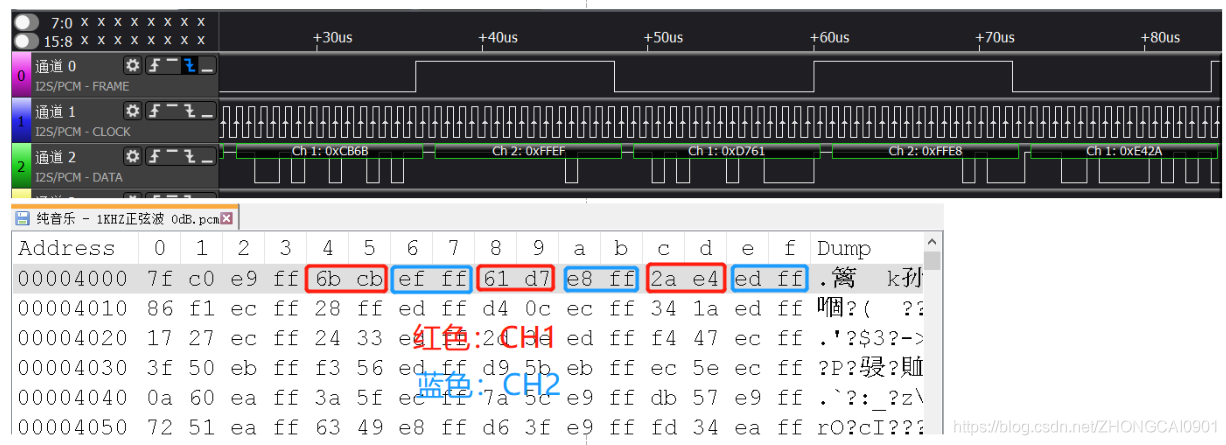
6. Data download
The download path of the complete engineering code successfully transplanted is as follows :
https://download.csdn.net/download/ZHONGCAI0901/18375355
边栏推荐
猜你喜欢


随机推荐
力扣解法汇总241-为运算表达式设计优先级
力扣解法汇总1175-质数排列
It took two hours to find the bug about scrollto scrolling the distance from offsettop to the top
垃圾回收
Why does chrome video get stuck badly (by quqi99)
Go 管道模式的实际例子——计算一系列文件的 md5 值
Go 语言学习:Go 语言之旅(三)
[10:00 public class]: cloud video conference system privatization practice
折腾凤凰系统 (by quqi99)
总结20220213(floyd和dijkstra)
堡垒机,DMZ区
Go 语言重要知识点:字符串、UTF-8 编码、rune
debug glance(by quqi99)
juju debug hacks (by quqi99)
Interview experience of Android Internet manufacturers
微信小程序本地访问本地TP5的路由接口正常,为何在手机上扫码预览获取不到数据?
枚举对象中属性
微信公众号网页授权----redirect_uri域名与后台配置不一致,错误码10003 错误
【Nordic】nRF52810 OTA升级(二)–DFU如何使用
力扣解法汇总498-对角线遍历